Hardware
Setting & Mode Configuration
Outside the unit, there is one 4-pin DIP switch which is set to select the mode of operation. You will need to set the switch settings to RS-232 mode, or RS-422, or RS-485 mode as per the requirements of your application.
The Mode Block Configuration Settings are listed as follows:
SW (External DIP Switch) for Mode Setting
|
|
Operation Mode |
S1 |
S2 |
S3 |
S4 |
|
RS-232 |
Standard RS-232 Mode |
OFF |
ON |
ON |
ON |
|
RS-422 |
4 wire with Handshaking |
ON |
ON |
ON |
ON |
RS-485 |
Full Duplex (4 wire) |
ON |
OFF |
ON |
ON |
|
Half Duplex (2 wire) - with Echo |
ON |
OFF |
OFF |
ON |
|
|
Half Duplex (2 wire) - without Echo |
ON |
OFF |
OFF |
OFF |
JP1 for Termination and Biasing Option Configuration
Inside the unit, there are eight 2 x 7 (14 pin) header blocks which are jumpered to enable Tx, Rx, CTS 120 Ohm termination resistors and Tx, Rx 750 Ohm BIASing resistor.
You will need to open up the metal case and set the jumper setting for RS-422 mode or RS-485 mode as per the requirements of your application.
Settings are listed as follows:
|
Jumper |
Function |
|
1-2 |
Tx Termination of 120 Ohm. This
jumper should always be populated for RS-485 mode. |
|
3-4 |
This
jumper should be populated for pull-up |
|
5-6 |
Pull-down
This
jumper should be populated for pull-down |
|
7-8 |
Rx
Termination of 120 Ohm. This
jumper should always be populated for RS-422 mode. |
|
9-10 |
Pull-up
Rx+ to VCC by 750 Ohm Bias resistor. This
jumper should be populated for pull-up Rx+ |
|
11-12 |
Pull-down
Rx- to GND by 750 Ohm Bias resistor. This
jumper should be populated for pull-down Rx- . |
|
13-14 |
CTS
Termination of 120 Ohm. This
jumper should always be populated for RS-422 mode. |
Note
: Sometimes, when operating in RS-422 or RS-485, it is necessary to configure
termination
and biasing of the data transmission lines. Generally this must be done
in
the cabling, since this depends on the installation of connections. Before
applying the option, check your cable specification for proper impedance
matching.
JP2 : Enable the +5V 150mA Power for External Device
The USB-COMi-M
provides a unique feature of supplying power output of 5V/150mA through
Pin-5 of terminal
block to the serial device requiring power. By default, this feature is
disabled. To enable the power, you need to open the metal case and set the
jumper (JP2) to the position of ��ON��.
|
Jumper |
Function |
|
ON |
Enable
the Terminal Block Pin-5 to support a 5V 150mA power for external device
requiring power |
|
OFF |
Disable
the 5V 150mA power (Default) |
RS-232/422/485
Pin-outs & Signal Wiring
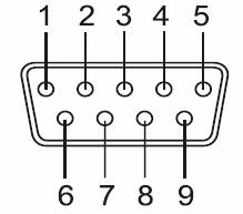
RS-232 Signal Pin-outs of DB-9 Male (CN2)
|
Pin 1 |
DCD |
|
Pin 2 |
RxD |
|
Pin 3 |
TxD |
|
Pin 4 |
DTR |
|
Pin 5 |
GND |
|
Pin 6 |
DSR |
|
Pin 7 |
RTS |
|
Pin 8 |
CTS |
|
Pin 9 |
RI |
RS-232 Signal Pin-outs of Terminal Block (TB1)
|
Pin 1 |
DCD |
|
Pin 2 |
RxD |
|
Pin 3 |
TxD |
|
Pin 4 |
DTR |
|
Pin 5 |
+5V |
|
Pin 6 |
GND |
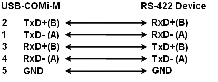
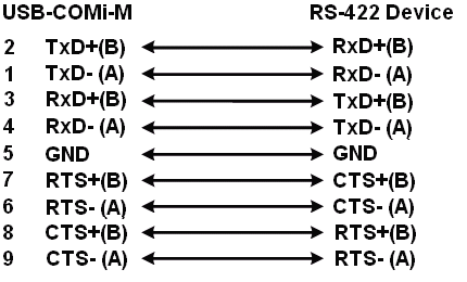
RS-422 Signal Pin-outs of DB-9 Male (CN2)
|
Pin 1 |
|
|
Pin 2 |
|
|
Pin 3 |
Rx+(B) |
|
Pin 4 |
Rx- (A) |
|
Pin 5 |
GND |
|
Pin 6 |
RTS- (A) |
|
Pin 7 |
RTS+(B) |
|
Pin 8 |
CTS+(B) |
|
Pin 9 |
CTS- (A) |
RS-422 Signal Pin-outs of Terminal Block (TB1)
|
Pin 1 |
|
|
Pin 2 |
|
|
Pin 3 |
Rx+(B) |
|
Pin 4 |
Rx-(A) |
|
Pin 5 |
+5V |
|
Pin 6 |
GND |