What is TTL?
TTL definition: Transistor-transistor logic, transistors performing both the logic gating and amplifying functions; a widely used technology for making integrated circuits.
Transistor-transistor logic or TTL is a digital logic design in which bipolar transistor(s) act on direct-current pulses. Many TTL logic gate s are typically fabricated onto a single integrated circuit (IC).
TTL circuitry, since the early 1960’s has been widely used in integrated circuit designs in computers, industrial controls and other consumer electronics. The TTL introduction into circuit design grew as new TTL concepts were developed for high-speed and power control such as lower power dissipation, because of the TTL design, doors were opened for other technologies to have an interconnection to benefit from its optimizing features.
The USB and TTL Connection
Because of its integration capabilities TTL has become somewhat of a foundation in integrated circuit (IC) design. TTL operation has extended into integration with USB and RS232 circuitry to provide serial interface from the UART interface. Logic gates at this point of integration are created to process and interpret information via a USB connection to the PC.
USB technology with TTL has played an important role allowing direct connections from the computer board’s pin header to be used for regular serial communication supporting RS232, . There is no “standard” TTL cable; you will sometimes find TTL a connection as wired ends, some with a connector on them as manufactures have tried to make it easy for data signal purposes.
In addition to “wired ends” (wire stripped of its jacket for connection reasons) TTL adapters are now being produced with power connectors and Dip switch control of voltage settings for an easy, user friendly control.
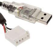 |
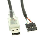 |
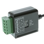 |
| USB interface with a 5-pin 5V TTL connector | TTL 3.3V with USB interface and 6 wire header pin connector | DIP switch voltage control for TTL wire to 5-wire terminal block |
TTL Voltage Parameters
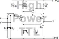
TTL connections vary from 3V to 5V signal operation in both input and output ranges. The voltage levels of TTL are designed to deviate substantially to cover both “high” and “low” values.
 |
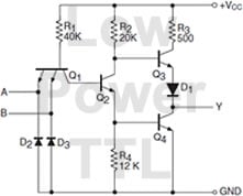 |
| High power TTL diagram | Low power TTL diagram |
Acceptable voltage ranges of TTL gate for input and output signal values is 0 to 5 volts overall but both the high and low signal levels need an acceptable amounts of voltage to perform at those levels, see below: (This information only pertains to the TTL gate itself and not the CMOS gate)
- Input low level signal requirement: 0V – 0.8V
- Output low level signal requirement: 0V – 0.5V
- Input high level signal requirement: 2V – 5V
- Output high level signal requirement: 2.7V – 5V
TTL Applications
There are a wide range of applications for which a TTL (Transistor-transistor Logic) integrated circuit is used, a brief list of these applications is listed below.
Serial communication, computers, industrial controls, test equipment and instrumentation, consumer electronics, synthesizers and more. More information can be found about TTL on the wiikipedia website.
